MAE 3303 Aerodynamics of Compressible Flow
Practice Final Exam
1. Derive expressions for CL, CD, and CMLE as functions
of a and t/c for the following airfoil:
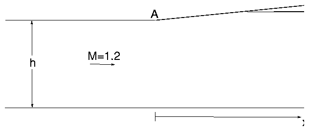
2. Consider the supersonic duct shown below.

By using only two waves emanating from the corner (point A)
estimate the following:
- Determine the point along the lower wall (x coordinate) where
the flow first feels the effects of the corner at point A.
- Determine the point along the lower wall (x coordinate) where
the flow last feels the effects of the corner at point A. (Exclude
secondary reflections off the upper wall for this part.)
- Determine the Mach number and pressure (p/p¥) for the
point determined in (b).
3. Compute the lift and drag coefficients for the triangular airfoil shown
below when M¥ = 2.0, a = 30, t/c = 0.2, and xh/c = 0.55. Use
the exact values of pressure behind shock waves and expansion fans (i.e. do
not use the small disturbance approximation).

4. A jet engine uses a supersonic nozzle to expand its exhaust gas to
p = 0.6 atm, which is the local ambient pressure. The engine delivers a
mass flow of 15 kg/sec, and the stagnation conditions of the exhaust gas
are p0 = 14 atm, T0 = 750 K.
- What is the required nozzle throat area?
- What is the pressure at the throat?
- What is the required nozzle exit area?
- What are the temperature and velocity at the nozzle exit?
- What changes in flow configuration (i.e. presence of shocks, expansion
waves, etc.) will occur if the engine and nozzle are operated at a lower
altitude where the pressure is 0.9 atm?
5. A wing has a zero Mach number lift curve slope of 8.34×10⁻² deg-1 and an
angle for zero lift of aL0 = -1.5 deg. The wing planform area is 510 m2.
- What is the wing lift coefficient when it is flying at M = 0.55, a = 2.1 deg?
- What angle of attack is required to produce a lift of 8.5×10⁵ N when
the flight conditions are M = 0.6, p = 0.5 atm, T = 230 K?
- The wing has a critical Mach number of Mcr = 0.71 when the angle of attack
is a = 4 deg. What is the minimum pressure coefficient for the wing at
a = 4 deg, M = 0?
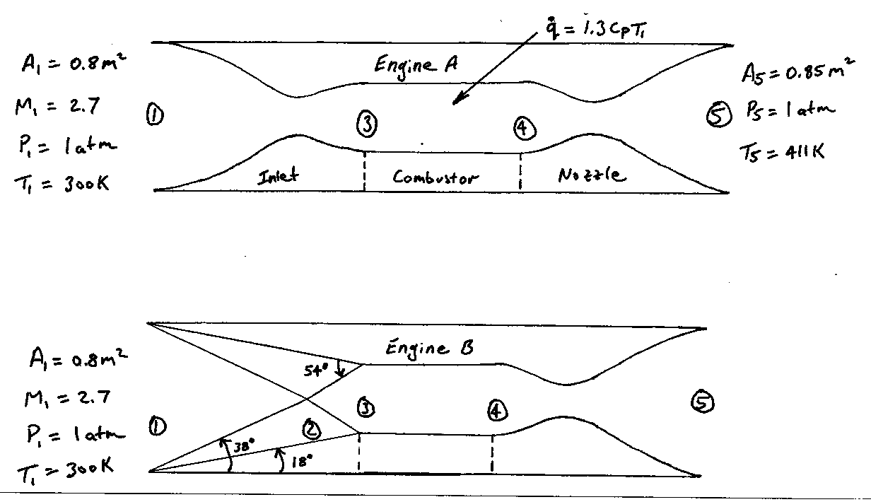
6. The stagnation pressure is a key parameter in the design of a supersonic
engine inlet. Consider the two engines sketched below. Engine A uses an
ideal inlet that is shock-free at the design condition, M=2.7.
Engine B uses a pair of oblique shocks to perform the compression. Answer
the following using the tables at the back of the book if that will save you
time. If you use the tables, do not bother to interpolate, just use the
closest entry to the data that you have.
Note: you will need to use the energy equation in the form
h0,4 = h0,3 + q for this problem. Also assume that inlet A will
start with the throat designed to be sonic.

- Compute p03/p01 for engine A.
- Verify that the shock angles are correct as shown for
engine B.
- Compute p03/p01 for engine B.
- Which inlet is better? Explain your answer.
- The pressure at the inlet to the combustor (station 3)
in engine A is 20 atm. Compute T, r, M, and u at this
station.
- The combustor in engine A adds heat in the amount
q = 1.3cpT1 and the temperature at the nozzle exit (station 5)
is observed to be T5 = 1.37T1. Compute the exit velocity (u5)
- Compute the thrust generated by engine A.
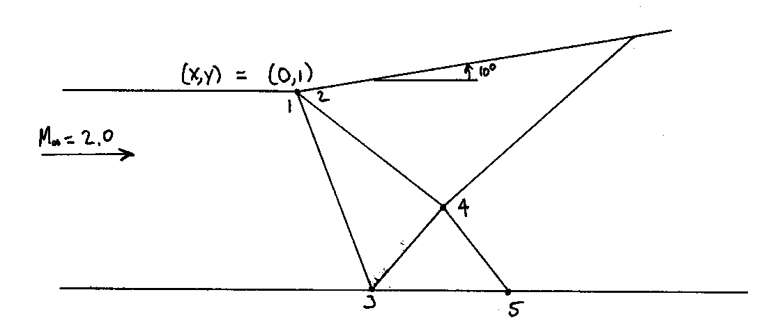
7. Consider the supersonic duct shown below.

Using the method of characteristics with just two waves representing the
expansion, fill in the following table. Take the leading wave to be the
first wave in the expansion fan and the following wave to be an intermediate
wave in the expansion fan where the Mach number is 2.2 at the corner.
Please show your work so I can give partial credit if necessary.
| point | q | n | M | K+ | K- | m | x | y |
| 1 | | | | | | | | |
| 2 | | | | | | | | |
| 3 | | | | | | | | |
| 4 | | | | | | | | |
| 5 | | | | | | | | |
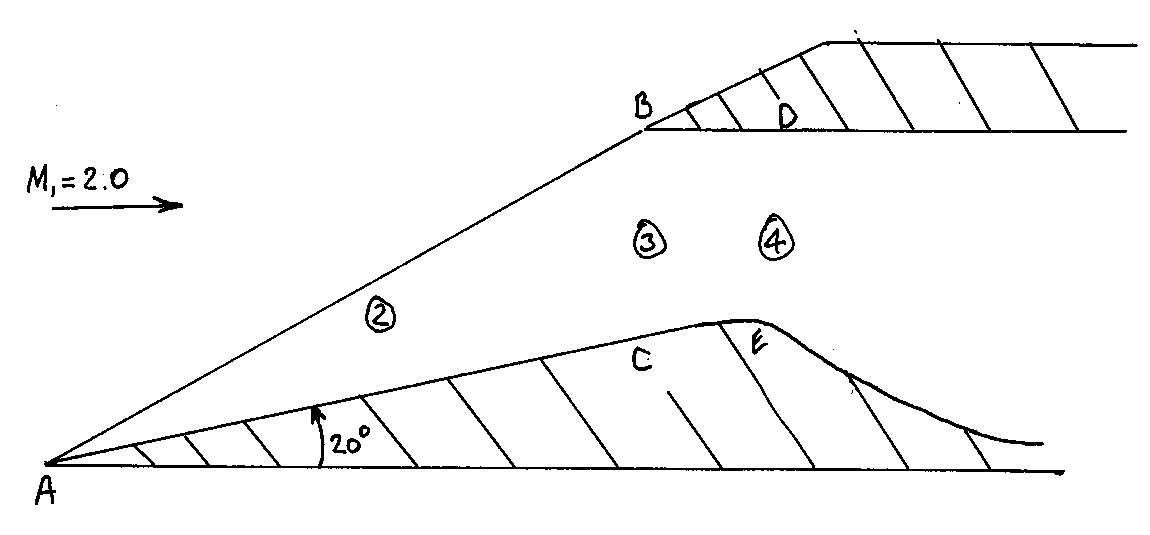
8. Consider a supersonic engine inlet that uses an
oblique shock to perform the initial stage of the compression as shown below.
Although the width of the inlet (distance into the paper) is only 0.5 meters,
assume that the flow can be approximated as being two-dimensional. Answer the
following for the design flight condition of M¥ = 2.0,
r¥ = 0.6 kg/m3, T = 240 K.

- Let the conditions behind the oblique shock be denoted by
subscript 2. What are the values of M2, p2, r2, and
p02/p01?
- Does the oblique shock reflect off the
wall at the point B as a normal or oblique shock? Explain your answer.
Draw this shock on the sketch.
- Let the conditions behind the second shock be denoted by
subscript 3. What are the values of M3, p3, r3, and
p03/p02?
- The engine requires a mass flow rate of 30 kg/s.
What should the distance measured between points B and C be in order
to supply the engine with the correct mass flux when is is flying at the
conditions stated above?
- What is the minimum permissible distance between
points D and E for the conditions considered above?
- Assume that the upper wall (containing points B and D)
can move fore and aft. Which way should the wall be moved if the flight
Mach number is increased to M = 2.5? Explain your answer.
File translated from TEX by TTH, version 2.00.
On 1 May 2001, 17:53.


